|
Product Details:
|
| Material: | Pu Nbr Ptfe | Package: | Bag Or Carton |
|---|---|---|---|
| Appliion: | Hydraulic Loader | Delivery Time: | 3-15 Days |
| Payment Terms: | T/T, Western Union | Performance: | Loader Cylinder Hydraulic Oil Sealing |
| Highlight: | 1428962 Breaker Seal Kit,7x2668 Breaker Seal Kit,7x2713 Arm Cylinder Seal Kit |
||
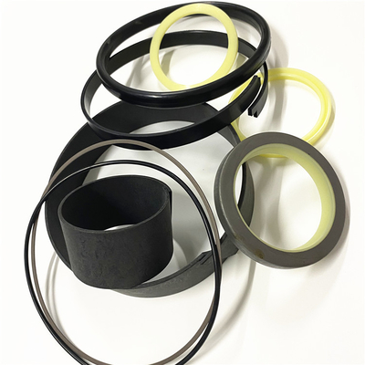
1428962 Breaker Seal Kit
1428962 2442080 2442070 2550913 1643213 7x2713 7x2668 8T1399 7X2706 7X2660 2285272 7X2704 2450585 7X2698 2442062 2450594
![]()
Improper lift rigging can allow unit to tumble causing injury and damage.
Never bend the eyebolts and the brackets. Only load the eyebolts and the brackets under tension. Remember that the capacity of an eyebolt is less as the angle between the supporting members and the object becomes less than 90 degrees.When it is necessary to remove a component at an angle, only use a link bracket that is properly rated for the weight.Some removals require lifting fixtures to obtain proper balance and safety.Lifting eyes are designed and installed for the specific engine arrangement. Alterations to the lifting eyes and/or the engine make the lifting eyes and the lifting fixtures obsolete. If alterations are made, ensure that proper lifting devices are provided. Consult your dealer for information regarding fixtures for proper engine lifting.Engine Lifting
The lifting instructions for lifting the engine will be loed in one of the following places:
A lifting instruction film will be on the front valve covers.
A lifting instruction tag will be attached to the front lifting eye.
Illustration 1 g00103219
Typical example of lifting with a spreader bar
Illustration 2 g06041976
(1) Engine lifting pointsUse a hoist to remove heavy components. Use an adjustable lifting beam to lift the engine. All supporting members (chains and cables) should be parallel to each other. The chains and cables should be perpendicular to the top of the object that is being lifted.To lift the engine, use the lifting eyes that are on the engine.The approximate dry weight of the engine is 13715 kg (30236.36 lb).The engines center of gravity (CG) is loed using the following dimension:
1408.5 mm (55.45265 inch) from the centerline of the crankshaft at the rear block face of the Z-axis toward the engine right-hand side
Y-axis vertical equals 261.7 mm (10.30 inch) from the centerline of the crankshaft
X-axis parallel equals 4.3 mm (0.17 inch) from the centerline of the crankshaftAftertreatment Exhaust Module Lifting
For more information on lifting the aftertreatment exhaust module, refer to the OEM of the exhaust module or locomotive manufacturer.The approximate weight of the exhaust module is 1850 kg (4079 lb).To lift the exhaust module, only use the lifting points that are on the exhaust module.
Illustration 3 g06092501
Aftertreatment Exhaust Module lifting points
Illustration 4 g06094925
(2) CEM cribbingNote: When setting CEM on the floor, ensure that the CEM is placed on cribbing (2) and the minimum distance from floor to CEM is 220 mm (8.6 inch). This distance is to prevent damage to the NOx sensor.
Contact Person: SUNNY
Tel: 86 18605253464


 English