|
Product Details:
|
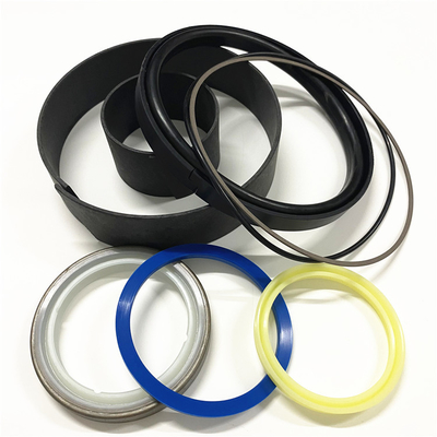
| Colour: | Yellow Or Blue | Material: | Pu Nbr Ptfe |
|---|---|---|---|
| Highlight: | O ring seals for industrial applications,High-performance O ring seals,Durable O ring seals with warranty |
||
2442076 2442079 2442080 2445647 2450579 2450580 2450581 2450582 2450583 2450584 2450585 2450586 2450588 2450589 2450590
CTP 245-0585 Cylinder & Rods (2450585) Aftermarket
Illustration 1 g06042397
(1) Nut
Table 1
Specifiion for Turbocharger
Item Qty Part Specifiion Description
2 - - Tighten the clamp bolt to 14.0 1.5 N m (123.9 13.3 lb in).
Hit lightly all around clamp with a soft faced hammer and again tighten to 14.0 1.5 N m (123.9 13.3 lb in).
A - - End play for the shaft is 0.165 0.063 mm (0.0065 0.0025 inch).
3 - - Clearance between the ends of oil seal ring (when installed in bore) is 0.20 to 0.38 mm (0.008 to 0.015 inch).
4 - - Tighten the bolts to 40 2 N m (30 1 lb ft).
B - - Bore in the bearings is 21.585 to 21.595 mm (0.8498 to 0.8502 inch).
Diameter of the surfaces (journals) on the shaft is 21.539 to 21.549 mm (0.8480 to 0.8484 inch).
C - - Bore in the housing is 30.594 to 30.607 mm (1.2045 to 1.2050 inch).
Outside diameter of the bearings is 30.467 to 30.480 mm (1.1995 to 1.2000 inch).
5 - - Before assembly, apply 5P-3931 Anti-Seize Compound to the threads.
Tighten the bolts that hold the turbine housing to the cartridge housing to 40 2 N m (30 1 lb ft).
Before assembly, apply 5P-3931 Anti-Seize Compound to the threads.
Tighten the bolts and nuts that hold the turbocharger to the exhaust manifold to 54 5 N m (40 4 lb ft).
CLOSE inlet and outlet ball valves.
Fully CLOSE inlet ball valve by moving handle (3a) away from the inlet pipe, as shown.
Fully CLOSE outlet ball valve by moving handle (20a) away from the outlet pipe, as shown.
Illustration 33 g02722607
Check both differential pressure gauge (5) follower needles for readings above 172 kPa (25 psi) to help identify which filter is restricted.Note: If differential gauge readings are normal, check for high water accumulation in sight glass (8). Use manual water drain valve (11) to remove water from coalescer vessel (7). Resume refueling operation.
If differential pressure gauges (5) indie restricted filters, refer to the Maintenance Section in this manual for filter element replacement procedures.
Illustration 34 g02722655
(18) Typical Slug Valve Shown in SET Position
Once all restrictions are corrected, reset slug valve (18) by moving lever from TRIPPED position to SET position.Note: If slug valve (18) will not reset, or immediately closes again, refer to the Troubleshooting Section in this manual, or contact your local dealer for assistance.
Slug valve is factory set to 172 kPa (25 psi) differential pressure. Do NOT adjust factory setting. Changing the setting can result in improper fuel filtration and damage to the bulk fuel filtration system components.
Note: To ensure fuel quality, have fuel cleanliness tested on a regular basis. For more information on fuel quality testing, refer to the latest version of SEBU6250 Machine Fluids Recommendations.Service Parts
Illustration 35 g02722674
(24) Typical Pre-filter Element (25) Typical Coalescer Element (26) Typical Separator Canister
Table 3
Service Parts
Item Part No Description Qty
24 284-0435 Pre-filter Element Kit (1) 1
25 284-0423 Coalescer Element Kit (2) 1
26 284-0426 Separator Canister (3) 3
307-0655 Optional Heater (120 VAC) 1
307-2569 Optional Heater (240 VAC) 1 Reference (1) Includes one pre-filter element and one pre-filter vessel o-ring seal. (2) Includes three coalescer elements and one coalescer vessel o-ring seal. (3) Separator canisters do not require replacement unless damaged or corroded.Troubleshooting
Table 4
Troubleshooting Chart
Problem Possible Cause Possible Solution
No fuel flow Inlet or outlet valve is closed Open inlet/outlet valve
Fuel hose is kinked Straighten hose and/or provide larger hose
Automatic slug valve shutdown Check differential pressure gauge follower needles for differential pressure reading. greater than
172 kPa (25 psi). The slug valve will close if filters are restricted. Change filter elements and reset slug valve.
Check sight glass for high water accumulation. Wait until system purges water or drain water manually. Reset slug valve.
Differential gauge reading greater than
69 kPa (10 psi) at start-up Air in the system Open vent valve at top of pre-filter vessel to release trapped air.
Differential gauge reading greater than
172 kPa (25 psi) Filter elements are restricted Replace filter elements and clean vessels. Reset slug valve if necessary. Maintenance Record
Replace filters at least every six months. Clean debris from vessels annually, or as needed
Off-Highway Truck/Tractor:
793F (S/N: SND1-UP; SSP1-UP)
Service Magazine, SEPD1413, 21 March 2012, "A New Shimming Procedure is Now Used on the Truck Bodies on 793F Off-Highway Trucks". Disregard this article. Refer to the article that follows.ReferenceDisassembly and Assembly, UENR2257, "793F Off-Highway Truck Field Assembly". A new shimming procedure has been developed for use on the listed machines. The new procedure can be used when the machine is assembled and when the body is installed. The new procedure can be used on the listed machines back to the beginning of production.For the new procedure, refer to "Install the 293-6301 Truck Body Mounting Gp " in the above listed document.
Contact Person: SUNNY
Tel: 86 18605253464


 English