|
Product Details:
|
| Material: | Pu | Color: | Yellow |
|---|---|---|---|
| Package: | Bag | Delivery Time: | 7-15 Days |
| Payment Terms: | T/T, Western Union | Appliion: | Hydraulic Loader |
| Highlight: | 7K9200 Dust Wiper Seals,7K9203 Dust Wiper Seals,7K9201 |
||
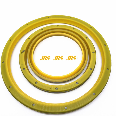
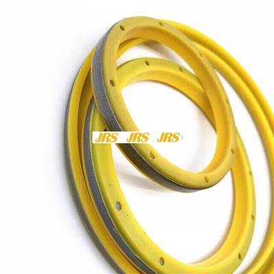
7K9200 Dust Wiper Seals
7K9200 7K9201 7K9202 7K9203 9204 9205 9206 9207 92097K9210 7K9211 7K9212 7K9213 7K9214 7K9215 7K9216 7K9217 7K9218 7K921
8H8969 - Link PIN Seal 7k9201 fits ()
FIRST PRICE PARTS
7K9210 SEAL-LIP TYPE parts 651E, 657E, 657G, 924K, 930K, 938K, 950 GC, 950B, 950B/950E, 950F, 950F II, 950G, 950G II, 950H, 953, 953C, 953D, 960F, 962G, 962G II, 962H, 966C, 966H, 966K, 966R, 972H, 972K, 977K, 977L, 992C, 992D
Compatible equipment models: 7K9210:
![]()
![]()
To prevent possible injury, do not use the starter to turn the flywheel. Hot engine components can cause burns. Allow additional time for the engine to cool before measuring valve clearance.
This engine uses high voltage to control the fuel injectors.Disconnect electronic fuel injector enable circuit connector to prevent personal injury.Do not come in contact with the fuel injector terminals while the engine is running.
Note: Valve lash is measured between the rocker arm and the bridge for the inlet valves. Valve lash is measured between the rocker arm and the bridge for the exhaust valves. All of the clearance measurements and the adjustments must be made with the engine stopped. The valves must be fully closed.Valve Lash Check
An adjustment is not necessary if the measurement of the valve lash is in the acceptable range. Adjust the valve lash while the engine is stopped. The range is specified in Table 1.
Put the No. 1 piston at the top center position on the compression stroke. Refer to Testing and Adjusting, "Finding Top Center Position for No. 1 Piston". To ensure cylinder No. 1 piston is at top center position compression stroke, both intake and exhaust valves on cylinder No. 1 will move freely. If the intake and exhaust valves do not move freely, cylinder No. 1 is on top center exhaust stroke. Install the timing pin in the flywheel.
Table 1
TDC No. 1 Compression Stroke Inlet Valves Exhaust Valves
Valve Lash 0.38 0.08 mm
(0.015 0.003 inch) 0.64 0.08 mm (0.025 0.003 inch)
Cylinders 1-2-4 1-3-5
Adjust the valve lash according to Table 1.
Lightly tap the rocker arm with a soft mallet. This action will ensure that the lifter roller seats against the base circle of the camshaft.
Loosen the adjustment locknut.
Place the appropriate feeler gauge between rocker arm and the valve bridge. Then, turn the adjustment screw in a clockwise direction. Slide the feeler gauge between the rocker arm and the valve bridge. Continue turning the adjustment screw until a slight drag is felt on the feeler gauge.
Tighten the adjustment locknut to a torque of 30 7 N m ((22 5 lb ft)). Do not allow the adjustment screw to turn while you are tightening the adjustment locknut. Recheck the valve lash after tightening the adjustment locknut. Remove the feeler gauge.
Remove the timing bolt and turn the flywheel by 360 degrees in direction of engine rotation. This will put the No. 6 piston at the top dead center position on the compression stroke. To ensure that cylinder No. 6 is at top dead center compression stroke, both intake and exhaust valves on cylinder No. 6 will move freely. If the intake and exhaust valves do not move freely, cylinder No. 6 is on top center exhaust stroke. Install the timing pin in the flywheel.
Table 2
TDC No. 6 Compression Stroke Inlet Valves Exhaust Valves
Valve Lash 0.38 0.08 mm
(0.015 0.003 inch) 0.64 0.08 mm (0.025 0.003 inch)
Cylinders 3-5-6 2-4-6
Adjust the valve lash according to
Contact Person: SUNNY
Tel: 86 18605253464


 English