|
Product Details:
|
| Size: | Standard Size And Customized,Standard/Nonstandard Size | Color: | Green,red |
|---|---|---|---|
| Material: | EPDM | Standard Or Nonstandard: | Hydraulic Pump Or Hydraulic Motors Oil Seals |
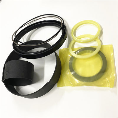
| Appliion: | Truck. Earth Moving Equipment | Product Name: | Hydraulic PU Polyurethane Urethane Oil Wiper Piston Seal,hydraulic V Set Textile Rubber Oil Seal |
| Highlight: | 7X2825 Hydraulic oil Seal Kit,2275350 Hydraulic oil Seal Kit,8T6390 Hydraulic oil Seal Kit |
||
Hydraulic Seal 7X2825 Compatible with 8T6892 8T6390 3769017 2275350 Seal kit
1 Kit Replacement Hydraulic Seal 7X2825 Compatible with 8T6892, 8T6390, 3769017, 2275350 | #AA84DL
GVII You Purchasing 1 Kit Replacement Hydraulic Seal 7X2825 Compatible With 8T6892, 8T6390, 3769017, 2275350 || 100% brand new and high quality || One New Replacement Fits Integrated Toolcarrier Steering Cylinder Seal Kit that fits the following model: IT38F, Cylinder: 1050094 || Please Note: Your Seal Kit will look different Replaces | Part Number: 1857025, 3769017, 2275350 || Rod: 1 3/4" | Bore: 3"
Replacement for Seal Kit 3769017 7X2825 Fits 657G 938F 938G 938GII HA770 HA771 HA870 HA871
KTTGYRE Replacement for Seal Kit 3769017 7X2825 Fits 657G 938F 938G 938GII HA770 HA771 HA870 HA871
![]()
The high voltage that is produced by an operating generator set can cause severe injury or death. Before performing any maintenance or repairs, ensure that the generator will not start.Place the engine control switch in the "OFF" position. Attach "DO NOT OPERATE" tags to all starting controls. Disconnect the batteries or disable the starting system. Lock out all switchgear and automatic transfer switches that are associated with the generator.
Use the following procedure in order to test the rotating rectifier.
Stop the generator set. Disconnect the wires for the AVR and isolate the wires for the AVR.
Make an assembly for separate excitation. The assembly can use a 12 volt battery or a variable DC power supply as a power source. Refer to Step 3 for an assembly that uses a 12 Volt battery. Refer to Step 4 for an assembly that uses a variable DC power supply.
Illustration 1 g01015807
1.(A) Exciter Field
2.(B) Diode (1 Amp)
3.(C) Rheostat (50 Ohms 300 Watts)
Connect a 12 volt battery in series with a rheostat (C) of "50 Ohms 300 Watts" and a diode (B) on both wires for the exciter field (5+ and 6-). Go to step 5.
Illustration 2 g01015808
4.(D) AC supply
5.(E) Variable power supply
6.(F) Exciter field
7.(G) Diode bridge
Connect a variable power supply and a diode bridge to both of the wires for the exciter field (5+) and (6-).
The assembly should have characteristics that are compatible with the power for the field excitation of the generator.
Operate the generator set at rated speed.
Gradually increase the current of the exciter field by adjusting the rheostat or the variable power supply. Measure the output voltage and the current at no load. Measure the output voltage and measure the current at no load.
The generator is operating properly when the output voltage is at the rated value and the output voltage is balanced within one percent for the rated level of excitation.
Contact Person: SUNNY
Tel: 86 18605253464


 English