|
|
Product Details:
|
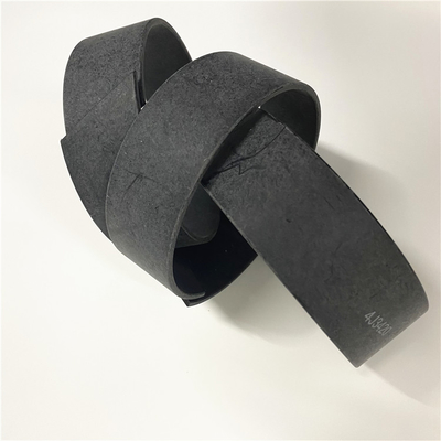
| Colour: | Black | Material: | Pu Nbr Ptfe |
|---|---|---|---|
| Highlight: | seal kit for heavy machinery,compatible seal kit 8C0543,durable seal kit with warranty |
||
8C0543 8C0544 8T8343 8T8344 9J5860 8T8347 4J7503 3G6537 8C4824 8C4825 5J0014 8T8348 7J5326 8T8349 8T8350 4T6930 8J1746
RING - WEAR FOR MITSUBISHI: 9J5860
MITSUBISHI || All Brand new & rebuilt items comes with 1 year warranty. || RING - WEAR FOR MITSUBISHI: Â FORKLIFT. MB9J5860 MB9J5860 MITSUBISHI 9J5860 MB 9J5860 9J5860 MITSUBISHI9J5860 Â Â Â Â Â Â THIS PART IS ALSO LISTED UNDER THE FOLLOWING PART NUMBERS:
7J5326 Ring Wear Fits 3306 3406 3406B 3406C 3408 3408C 3408E 3508B
![]()
Conditions Which Generate This Code:
Illustration 1 g01248848
Schematic of the Transmission Oil Temperature SensorThis diagnostic trouble code is associated with the transmission oil temperature sensor. The FMI 00 means that the ECU has determined that the signal of the sensor is above the normal range. The possible causes of this diagnostic trouble code are listed below:
The sensor has failed.
The signal circuit of the sensor is shorted to the + battery circuit.
The sensor needs to be calibrated.
The ECU has failed. This is unlikely.Note: The following test procedure may create other diagnostic trouble codes. Ignore these created diagnostic trouble codes and clear the diagnostic trouble codes when the original diagnostic trouble code has been corrected.Note: Use a digital multimeter for the measurements in this procedure.Test Step 1. INSPECT THE SENSOR
Perform a visual inspection of the sensor, the wiring for the sensor and the hardware that is associated with the sensor.Expected Result:There is no apparent damage to the sensor, the wiring for the sensor or the hardware that is associated with the sensor.Results:
OK - There is no apparent damage to the sensor, the wiring for the sensor or the hardware that is associated with the sensor. Proceed to Test Step 2.
NOT OK - There is apparent damage to the sensor, the wiring for the sensor or the hardware that is associated with the sensor. Repair: Replace the damaged part. Proceed to Test Step 2.Test Step 2. CHECK FOR POWER AT THE SENSOR
Do not disconnect the harness connector from the sensor.
At the back of the harness connector for the sensor, insert a multimeter probe along the voltage supply wire contact A.
Turn the key start switch and the disconnect switch to the ON position.
Measure the voltage from contact A to frame ground.Expected Result:The voltage is 8 volts.Results:
OK - The voltage is 8 volts. Proceed to Test Step 3.
NOT OK - The voltage is not 8 volts. The circuit is open. Repair: Repair the machine harness or replace the machine harness.STOPTest Step 3. CHECK FOR PROPER GROUND AT THE SENSOR
The machine harness remains connected to the sensor.
Turn the key start switch and the disconnect switch to the OFF position.
Remove the multimeter probe from the voltage supply wire contact A.
At the back of the harness connector for the sensor, insert a multimeter probe along the ground wire contact B.
Measure the resistance from contact B to frame ground.Expected Result:The resistance is less than 5 ohms.Results:
OK - The resistance is less than 5 ohms. The ground circuit is correct. Proceed to Test Step 4.
NOT OK - The resistance is greater than 5 ohms. The ground circuit in the machine harness has failed.Repair: Replace the machine harness or repair the machine harness.STOPTest Step 4. CHECK THE SIGNAL OF THE SENSOR
Turn the key start switch and the disconnect switch to the OFF position.
The multimeter probe remains along the ground wire contact B.
At the back of the harness connector for the sensor, insert the other multimeter probe along the signal wire contact C.
Turn the disconnect switch and the key start switch to
Contact Person: SUNNY
Tel: 86 18605253464


 English