|
Product Details:
|
| Material: | PU | Standard Or Nonstandard: | Standard |
|---|---|---|---|
| Color: | Red | Product Name: | Buna Nitrile Rubber 80 90 Shore A Hardness,Dust Wiper Seals DKB/DKBI/DLI/OUY/UN For Excavator Hydraulic Cylinder |
| Style: | Oil | Size: | Custom Size |
| Highlight: | 2332625 Cylinder Seal Kit,2332623 Cylinder Seal Kit,Cylinder Seal Kit 2332624 |
||
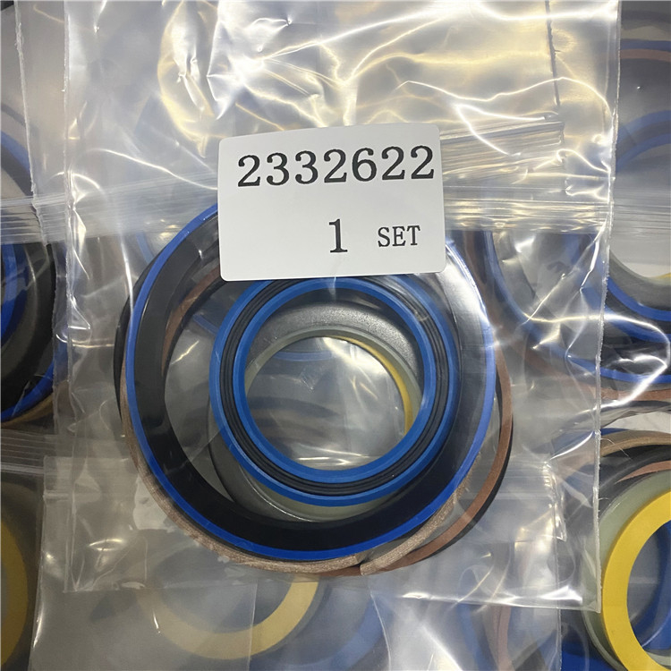
2332622 2332623 2332624 2332625 Cylinder Seal Kit Fits Fits
One New Cylinder Seal Kit Fits , Fits 416D, 416E, 420D, 420E, 430D, 430E Models Interchangeable with 2332623, 2332623-A
Stevens Lake Parts One New Aftermarket Replacement || This Is An Aftermarket Replacement Part Made To Meet Or Exceed OEM Specifiions. || Please Note That OEM Part Numbers, Models, & Dimensions Are Intended For Your Cross-Reference. Feel || Some Listings Use Stock Images For Customer Reference, Please Allow For Slight Differences.
One New Cylinder Seal Kit Fits , Fits 416D, 416E, 420D, 420E, 430D, 430E Models Interchangeable with 2332622, 2332622-A
Stevens Lake Parts One New Replacement || This Is An Aftermarket Replacement Part Made To Meet Or Exceed OEM Specifiions. || Please Note That OEM Part Numbers, Models, & Dimensions Are Intended For Your Cross-Reference. Feel || Some Listings Use Stock Images For Customer Reference, Please Allow For Slight Differences.
![]()
3. Plate assembly. 4. Shim pack.3. Put plate assembly (3) in position in the bore of the flywheel to check for clearance. There must be clearance between the outside diameter of the plate assembly (3) and the inside diameter of the bore in the flywheel.
Damage to the engine and/or generator can be the result if the electric set is run with a plate assembly that does not have this clearance.
4. Install a full shim pack (4) and plate assembly (3) on the generator with bolts (5). On D379, G379, D398, G398, D399 and G399 engines, tighten bolts (5) to a torque of 370 35 lb. ft. (505 45 N m). On all other engines, tighten bolts (5) to the standard torque.
INSTALL PLATE ASSEMBLY
5. Bolt.1. Pulley. 2. Key. 3. Bolt. 4. Retaining ring. 5. Shaft.2. Remove the three bolts (3) holding the pulley (1) to the retaining ring (4) and insert the bolts into the threaded pusher holes of the retaining ring as illustrated.3. Tighten the bolts into the retaining ring, forcing the ring out of the pulley and off the shaft (5). The key (2) secures the pulley to the shaft and also prevents the slotted retaining ring from rotating. When installing the pulley, the slotted retaining ring acts as a clamp on the shaft.4. Install in the reverse order of removal.
ENGINE FLYWHEEL
6. Guide bolt.
PUT GENERATOR IN POSITION
INSTALL BOLTS
Contact Person: SUNNY
Tel: 86 18605253464


 English