|
Product Details:
|
| Usage: | Engine | Packing: | Carton Box |
|---|---|---|---|
| Oem: | Accpetable | Colour: | Black |
| Material: | Pu Nbr Ptfe | Clour: | Black |
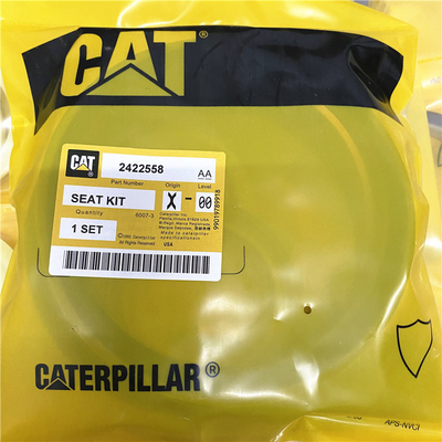
| Highlight: | 2422558 Seal Kits,7X2836 Seal Kits |
||
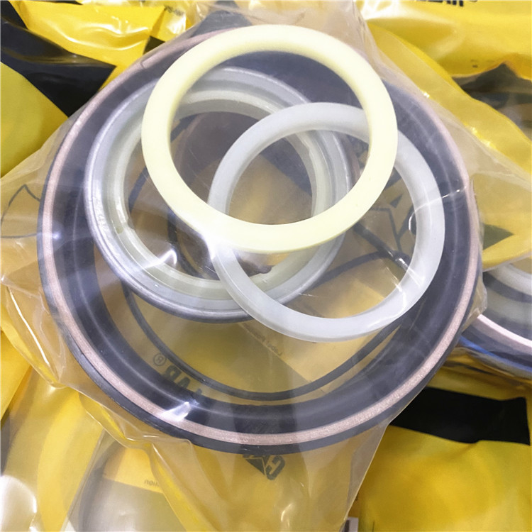
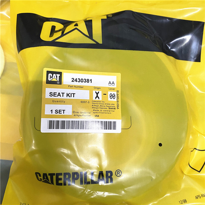
Seal KIT 2422558 2280808 2430381 fits 980G 980G II 980H 7X2655 7X2836
9X2050 - Seal KIT 1864356 8T1374 3367352 2430381
2280808 KIT-SEAL parts 980G, 980G II, 980H
1864351 - Seal KIT 2422558 7X2836 fits ()
2430381 Aftermarket Hydraulic Cylinder Seal Kit by Kit King USA
2.5 Inch Rod & 5.5 Inch Bore || Equipment Types: Scrapers & More || Equip. Models: 12F, 14E, 16, 621/B, 623/B, 627/B, 824/B, 922A/B, 941/B, 944/A, 950, 951B, 951C, 955, 955K/L, 977K/L, 980B, 992, 992B, D4D, D4E, D5B, D6D, J621 & More || Typical Hydraulic Appliions: Bucket, Lift, Load, Ripper, Tilt || Cylinders: 5J6342, 6J3308, 7J9690, 7J9695, 7J9741, 7J9742, 8J0204, 8J5761, 8J9446, 9J2399, 9J2401, 9T1803 & More
Specifiions
| Appliion: | Load Cushion Hitch |
| Bore Diameter: | 6 in |
| Unique parts: | 7 |
| Weight: | 0.50 lbs |
| Rod Diameter: | 2.50 in |
| Total Parts: | 7 |
| Interchange Number: | 7X2655 |
| Interchange Number: | 7X2836 |
| Interchange Number: | 1864351 |
![]()
![]()
![]()
The crankshaft is a chrome-molybdenum forging. The crankshaft has five main journals for four cylinder engines and seven main journals for six cylinder engines.End play of the crankshaft is controlled by two half thrust washers that are loed on both sides of the center main bearing.The main bearings are made with a steel back and a bearing material. The bearing material is constructed of an aluminum and tin alloy. The exception is the center main bearing, which is lead bronze with a lead finish. The main bearing caps are made of cast iron or spheroidal graphite (SG) iron.Vibration Damper
The vibration damper is designed as aAccidental engine starting can cause injury or death to personnel working on the equipment.To avoid accidental engine starting, disconnect the battery cable from the negative (−) battery terminal. Completely tape all metal surfaces of the disconnected battery cable end in orderombustion chamber.The fuel injector is cooled by fuel which is routed through the engine cylinder head. Low-pressure cooling fuel enters the injector between O-rings (2) and (3). Low-pressure cooling fuel exits with internal leakage fuel between the bottom O-rings (3) and (5).
Illustration 2 g06201679 to prevent contact with other metal surfaces which could activate the engine electrical system.Place a Do Not Operate tag at the Start/Stop switch loion to inform personnel that the equipment is being worked on.
Contact Person: SUNNY
Tel: 86 18605253464


 English