|
Product Details:
|
| Material: | NBR,PU,20CrMo | Appliion: | Excavator |
|---|---|---|---|
| Type: | Side/Top/Box-Silence | Style: | O Ring |
| Highlight: | black wear ring for loader,hydraulic cylinder seal kit,loader seal kit with wear ring |
||
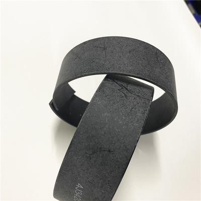
8C9120 8T5443 3J9027 8T8205 BLACK WEAR RING FOR LOADER SEAL KIT
8T8205 RING-WEAR parts 267, 930R, SS-250
3J9027 RING parts 235, 235B, 235C, 235D, 836, 966C, 977, 977D, 977H, 977K, 980, 988
8C9120 RING-WEAR parts 930R
8T5443 RING-WEAR parts 120G, 12G, 130G, 140G, 160G, 508, 910, 916, 926, D3C III, D3G, D4C III, D4G, D5C III, D5G, IT12B, IT28B
3J9027 | Wear Ring
HHP provides parts equal or better in quality compared to the OE at a fraction of the cost. || Products are crafted with hard-wearing materials for long-lasting strength and durability. || Parts meet or exceed OEM specifiions to ensure proper fit and function. || Image(s) is for illustration purposes only and may not represent the actual part. || Products are only sourced from quality certified manufacturing facilities.
![]()
![]()
Installation Procedure
Table 1
Required Tools
Tool Part Number Part Description Qty
A 5P-3931 Anti-Seize Compound -
Keep all parts clean from contaminants.Contaminants may cause rapid wear and shortened component life.
Illustration 1 g01199991
Attach a suitable lifting device to turbocharger (5). The weight of turbocharger (5) is approximately 35 kg (77 lb). Apply Tooling (A) to the threads of bolts (11) and the bearing surfaces. Install gasket (9). Position turbocharger (5) on the engine. Install bolts (11) and nuts (10). Use the following procedure in order to tighten nuts (10) :
Tighten all of the nuts on the joint to a snug fit.
Tighten one nut to a torque of 54 5 N m (40 4 lb ft).
Tighten the diagonally opposed nut to a torque of 54 5 N m (40 4 lb ft).
Tighten the remaining nuts to a torque of 54 5 N m (40 4 lb ft).
Repeat Steps 1.b to 1.d.
Illustration 2 g01199989
Apply Tooling (A) to the threads of bolts (6) and the bearing surfaces. Position bellows assembly (7) on exhaust elbow (8) and turbocharger (5) .
Install bolts (6) and tighten the bolts to a torque of 54 5 N m (40 4 lb ft).
Illustration 3 g01199987
Install tube assemblies (3). Connect tube assemblies (4) .
Illustration 4 g01199984
Connect hose assemblies (2) and (1) .
Fill the cooling system with coolant. Refer to Operation and Maintenance Manual, "Coolong System Coolant - Change".End By: Install the air cleaner. Refer to Disassembly and Assembly, "Air Cleaner - Remove and Install".
Contact Person: SUNNY
Tel: 86 18605253464


 English